Twentieth Anniversary Macintosh
Comprehensive Disassembly Guide
Disassembly Overview
Disassembly of the TAM is complex and difficult - please only attempt this if you know what you are doing. For context, it took me roughly 1.5 hours to complete a full disassembly of my machine, including both the head and base units, though much of this time was due to missing steps or other issues with the online guides that existed at the time.
I highly recommend reading through this entire guide BEFORE beginning, so that you can anticipate what you’ll be doing and ensure you’re prepared.
I also highly recommend using some kind of organizer to store the various fasteners, brackets, and other parts that this disassembly procedure will generate. There are MANY of them, and they are all different.

Head Unit (Computer)
This guide is an adapted version of the iFixit TAM teardown guide, but adds several critical missing steps.
Click here to view full-size versions of the images in this guide.


Step 1: Power off the TAM, disconnect the umbilical cord and any peripherals, and rotate the head unit so that its back is facing you.
Press upwards on the two release tabs at the bottom-rear to release the back cover.
Step 2: Remove any expansion or communications cards that are installed, along with their riser cards and the side faceplate.
Step 3: If it is present, unplug and remove the PRAM battery from its Velcro pad.
Unplug the CPU fan from the motherboard.
Remove the four Phillips screws securing the hard drive and CPU fan assembly to the chassis, and remove the assembly.
Step 4: Remove the two Torx screws securing the A/V input board, and lift the board out.
Step 5: Remove the white plastic shield that was behind the A/V input board, and also remove the Torx screw holding the logic board to the chassis.
Step 6: Remove the grated rear panel at top-rear of the TAM. To do this, GENTLY flex the part by pulling upwards from the center-bottom and work it upwards and side to side. Use firm but gentle pressure to release it from its clips.
For reference, here is a rear view of what the clips look like.
Step 7: Remove the two Torx screws revealed behind the grated panel.
Step 8: Rotate the head unit so that the front is facing you.
Use a spudger to gently pry the two speaker covers from their press-fit snaps. Remove the speaker covers.
Step 9: Remove the six Torx screws securing the front case to the rear case.
Step 10: There are four main case clips to release. To do this, use a spudger to gently pull each tab towards the center of the head unit. These tabs are fragile and may break but sometimes they release easily. Use caution and be patient.
Once all four of the clips are released, the front of the TAM should be loose. Tilt the top of the front assembly forwards and lift slightly upwards to release the latches on the bottom of the head unit.
DO NOT TRY TO REMOVE THE FRONT CASE YET. It is still connected to the back case by several wires and cables.
A NOTE PRIOR TO PROCEEDING: The optical drive door latch mechanism - the large black bar on the rear of the front fascia - becomes partially exposed once the front fascia is pulled away. If your optical drive door’s plastic hinges are still intact, BE CAREFUL not to accidentally knock this bar, as the door will pop open, making it easy to knock it sideways and break the hinges. The hinges are VERY fragile and will break easily if the door receives moderate sideways force.
Step 11: Time to disconnect some cables.
On the right side, disconnect the pink and white display cable and the black and white right speaker cable.
You should now be able to swing the front assembly to the left to access the connectors on the left side.
Next, disconnect the flat orange display cable near the top of the left side.
Lower down on the left side, disconnect all three cables from the back of the CD-ROM drive. Then, disconnect the black and white left speaker cable and the black and white microphone cable.
Then, disconnect the large ribbon cable from the interconnect board.
The front assembly should now be free. Remove it from the chassis.
Step 12: Now it’s time to begin removal of the logic board, tuner card, and ribbon cable assembly.
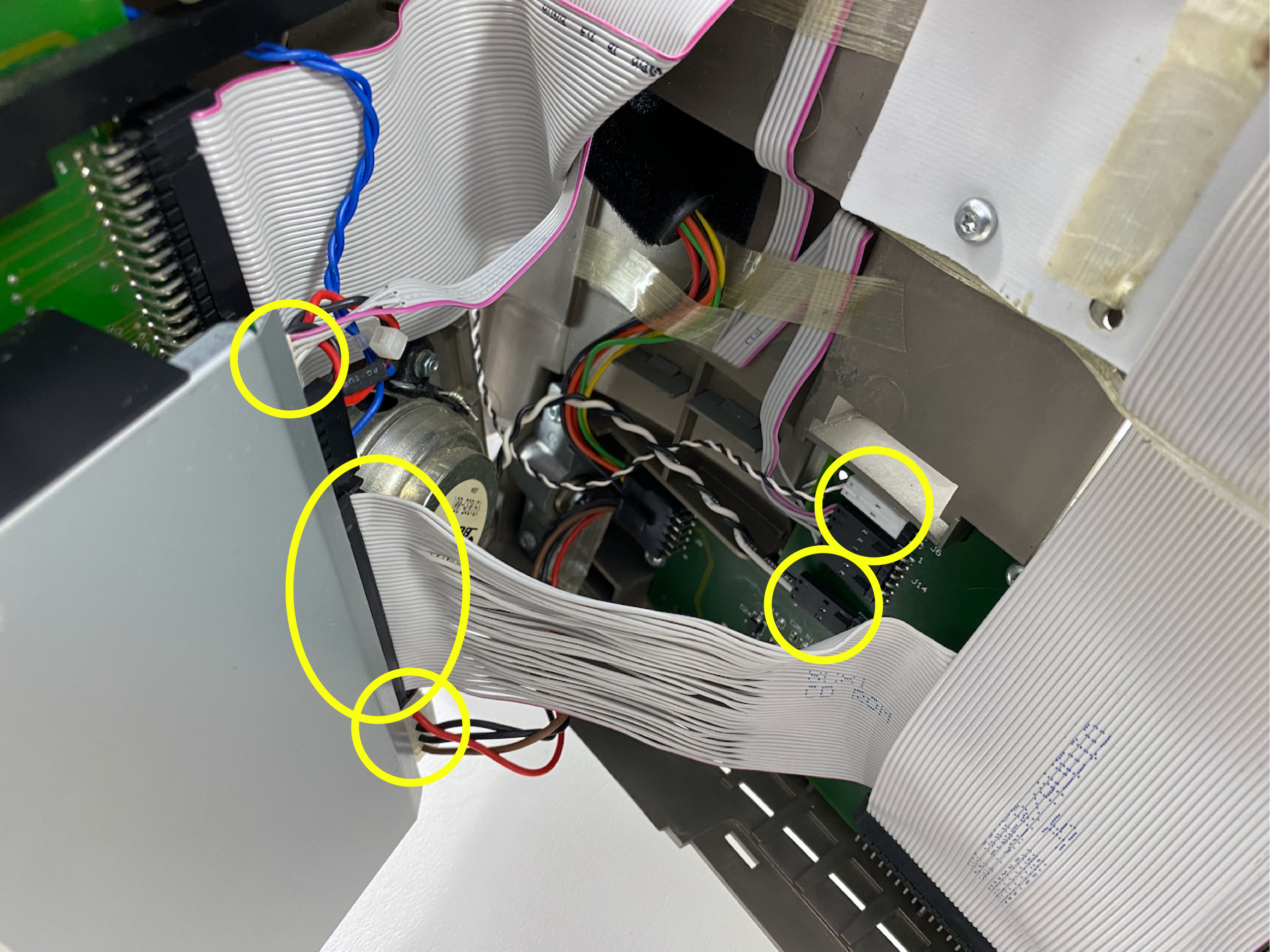
To do this, first disconnect the seven cables circled here (five cables and two coaxial connections).
Step 13: On the left side, remove the single Torx screw and lift away the wire cable support.
Step 14: Peel away the mass of ribbon cables by unsticking the various pieces of tape from the white logic board cover. I recommend trying to preserve the tape (keep it attached to the ribbon cables) so it can be re-used, and so that the cables maintain their configuration and shape.
Remove the five Torx screws holding the logic and tuner boards to the back case. Note that several of these screws have small metal pieces that must be re-attached during reassembly.
Gently lift the logic board, tuner card, and ribbon cable assembly up and to the right to remove it.
**Reassembly note: make sure to reattach the ground cable loop while reinstalling the screw for the lower right side of the tuner card.
Step 15: Remove the large grey edge connector receiver from the logic board, which will free the logic board from the mass of ribbon cables and the tuner card.
Congratulations, you have successfully extracted the motherboard!
Proceed ONLY if you need to completely disassemble the head unit for additional servicing.
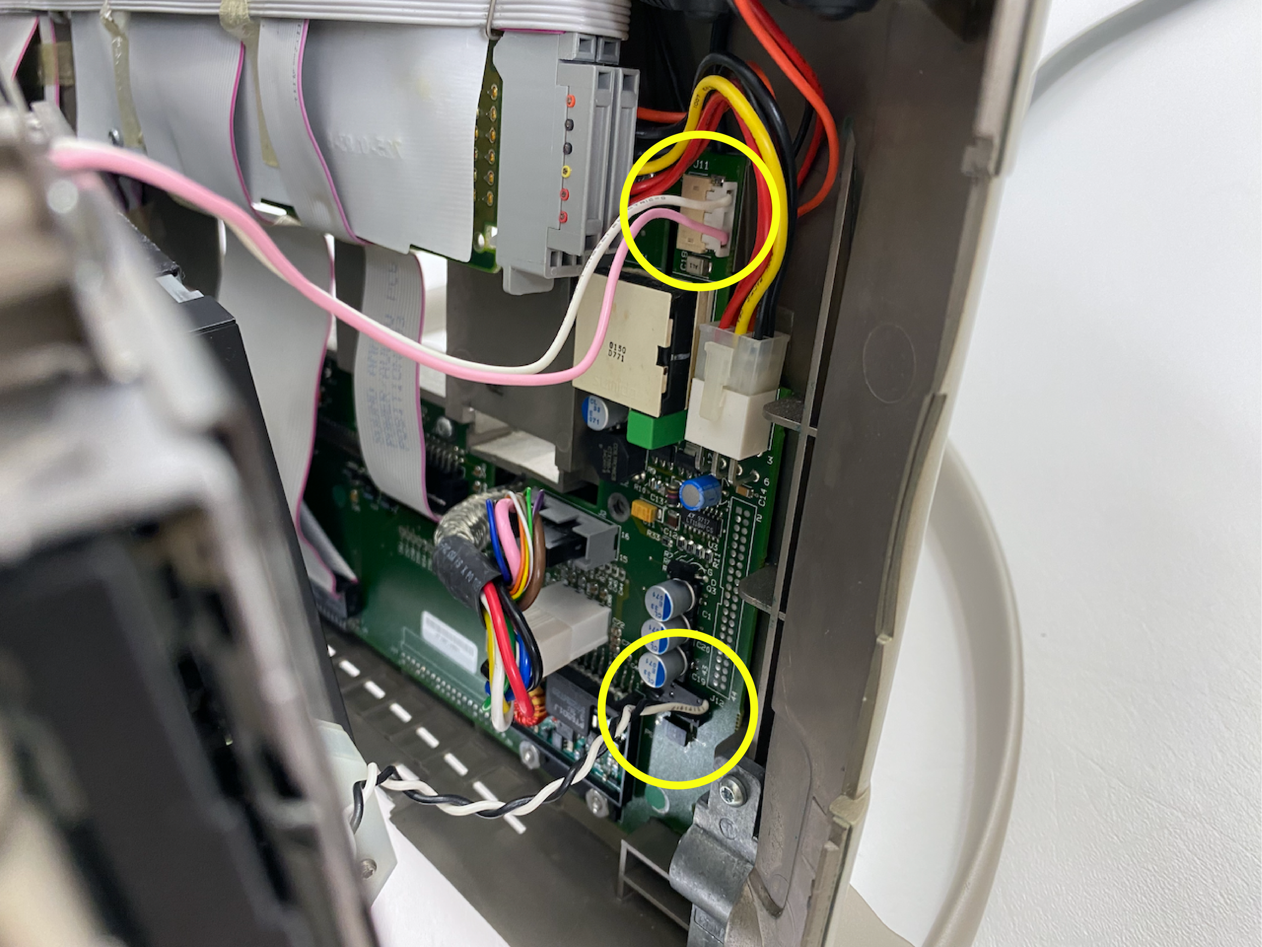
Step 16: To remove the power distribution board, first disconnect these four cables.
Then, remove the five Torx screws holding the power distribution board into the rear housing. Note that one of them is hidden behind some wires.
Remove the board from the housing.
**Reassembly note: be sure to re-route the two coaxial cables through these slots prior to reinstalling the power distribution board.
Step 17: To access the case fan in the rear housing, first remove the inverter board.
To do this, remove the two Torx screws and disconnect the single remaining connector from the board.
Remove the board from the rear housing. You should now be able to see the fan.
Step 18: Remove the two captive Torx screws from the fan bracket.
The bracket and fan should come free.
To re-assemble the TAM, follow these instructions in reverse, paying special attention to ensure that components and brackets are installed in the right order and juxtaposed correctly.
If you have feedback on this disassembly guide, or suggestions for its improvement, please shoot me an email!
Base (Bass) Unit
This disassembly guide is loosely based on a great video by iiiDIY. Note that the video only proceeds as far as is required for the “Bose buzz” fix, and it does not clearly document every step of the process.
Click here to view full-size versions of the photos in this guide.

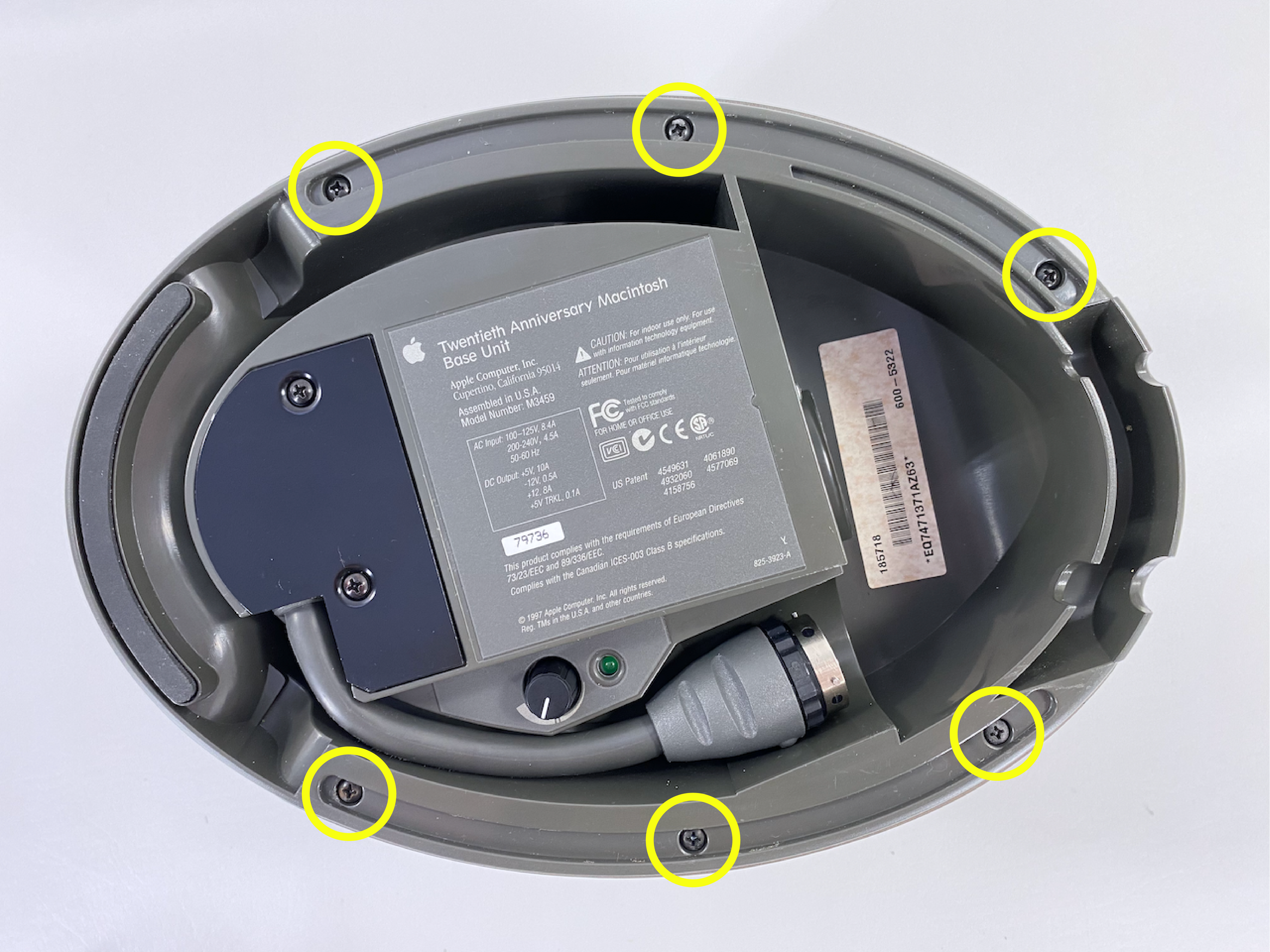


Step 1: Flip the base unit over so that it rests on its top.
Peel away the two rubber strips on the sides of the bottom. Note that they are different lengths.
Step 2: Remove the six Phillips screws that were underneath the strips.
Step 3: Remove the bass volume adjustment knob by pulling straight upwards. It should pop right off.
Step 4: Flip the base unit over so that it rests on its bottom.
Remove the decorative “cap” and underlying piece of metal and fabric on the top of the unit by pulling straight up, gently but firmly.
The cap is held on by three plastic posts. In my case, all three of them broke off. If this occurs, the cap can be re-attached with superglue (it is merely decorative).
Step 5: Remove the rubber dome on the top of the base unit.
To do this, use a spudger or other blunt tool to break the seal on the adhesive which extends around the outer lip behind the rubber. Once the seal is broken, keep pressure on it and work your way around with the spudger. Be careful not to mar the paint on the top edge around the unit.
The dome should eventually come free. Mine was still very flexible so this was no issue.
Step 6: Remove the two Phillips screws at the top rear of the base unit.
Step 7: Separate and remove the outer shell of the base unit. You may need to flip it over to push from the bottom edge.
The internals of the base unit should now be exposed.
Step 8: Disconnect the two cables from the Bose amplifier board.
Step 9: Peel back the circle of sound-insulating foam on the sound board bracket at the top of the PSU. Remove the single Phillips screw that is revealed, and lift the board out of the base unit.
**Reassembly note: Be cautious not to knock off the very thin and fragile plastic posts that the Bose board slides into.
If you are implementing the “Bose buzz” fix, congratulations - this is as far as you need to proceed!
The spade connectors on the subwoofer connection should now be exposed at the rear. These can be disconnected for replacement without any further disassembly of the base unit.
Proceed to the next step ONLY if you are completely disassembling the base unit for further servicing.
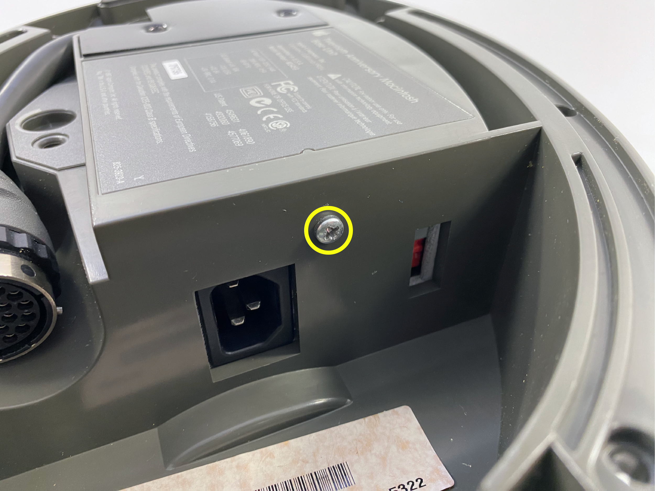
Step 10: The PSU is the next thing to remove. To do this, first remove the single Phillips screw located near the mains input on the bottom of the case.
Step 14: Remove the three Phillips screws securing the subwoofer to the case.
Remove the subwoofer from the lower case.
The subwoofer cable should subsequently be freed, so it can also be removed.
**Reassembly note: make sure to route the subwoofer cable back through the groove in the case, ensuring that the lengths are the same on each side. The original location should be obvious by the dent/folds in the black foam. This cable cannot be moved once the subwoofer is reinstalled.
Also make sure to reinstall the subwoofer in the same orientation, with the connectors on the bottom.
To re-assemble the TAM, follow these instructions in reverse, paying special attention to ensure that components and brackets are installed in the right order and juxtaposed correctly.
If you have feedback on this disassembly guide, or suggestions for its improvement, please shoot me an email!
Step 11: Remove the two Phillips screws from the the black metal plate on the bottom of the case.
Push downwards from inside the case to pop the plate off. Note that substantial force may be required, as the plate may be “stuck” to the case with sound-insulating foam. It should eventually pop right off.
Step 12: Free the square rubber grommet on the umbilical cord from its grooves by lifting it upwards. The PSU should now be completely freed from the lower case.
Feed the umbilical cable through the hole, and remove the PSU, being careful not to snap off any of the fragile plastic posts inside the lower case.
Step 13: Remove the spade connections from the speaker terminals by pulling straight back on them.
Note that replacement connectors are shown here, which have plastic covers. These are not present on the original connectors.
Additional Teardown Photos

Front view of stripped TAM head unit chassis. The remaining components are held in place with a single screw or with tape.

Close-up of remaining ports and cables in head unit chassis. These can be removed by unscrewing them from the rear case.

Ribbon cable, edge connector, HD adapter, and tuner card assembly. The tuner card is not easily disconnected from the ribbon cables.

Close-up of the large edge connector for the motherboard. The TAM uses a slightly modified version of the Power Macintosh 6500 board, which is why the edge connector is present. The fact that this board was shoehorned into the TAM with this large, awkward edge connector receiver and oodles of ribbon cabling are a testament to the suboptimal ways in which the TAM was put together - but a bespoke board would have likely been too costly to justify for a machine with such a limited production run.

Left side view of base unit internals, showing the top of the large PSU fan.

TAM PSU fan.

Stripped base unit chassis. All of this glue was factory-original.

TAM Bose subwoofer. It sounds fantastic at any volume.
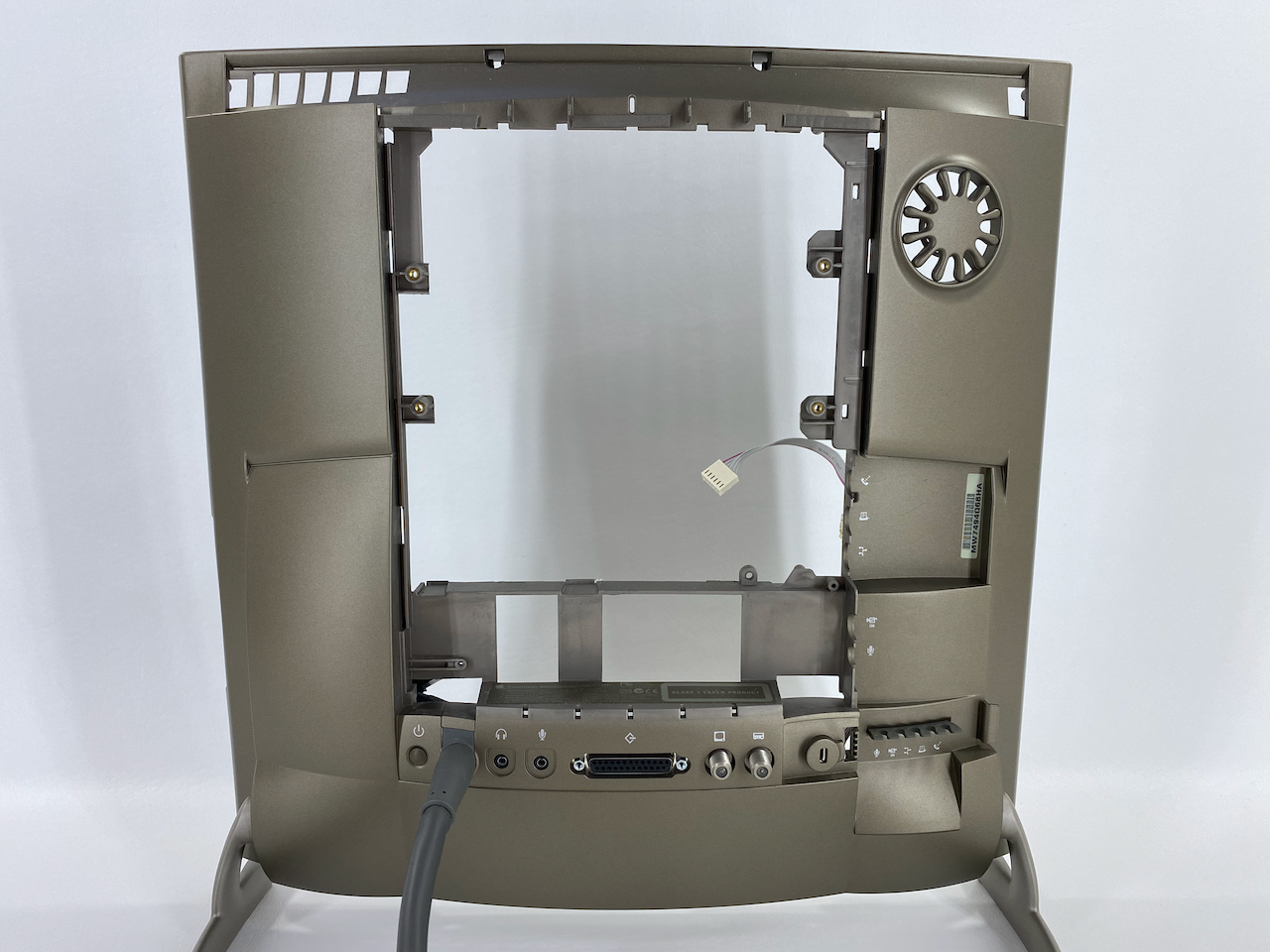
Rear view of stripped TAM head unit chassis. This angle shows how any plastics not normally visible are unpainted (not bronze).

Rear of the front case, showing part of the interconnect board (green) for the floppy drive (shown at left) and front buttons/lights.

Close-up of FM radio and TV tuner card. The small card fastened atop it with the white plastic sleeve is the HD adapter board.
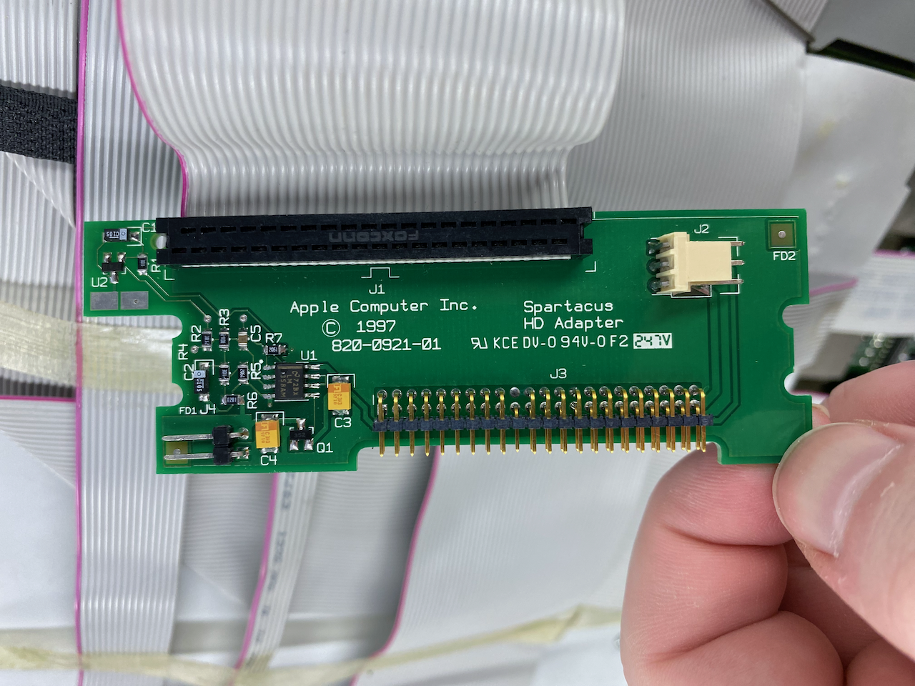
Close-up (photo taken sideways) of the “Spartacus HD Adapter” disconnected from the ribbon cable assembly (it is normally strapped to the tuner card). “Spartacus” was the internal code name for the TAM. The two-pin header at bottom-left is for the case fan, the three-pin header (J2) is for a cable that supplies power from the distribution board, and the large header (J3) attaches the IDE cable for the hard drive. The remaining ribbon cable still attached here appears to be permanently affixed and is not easily removable.
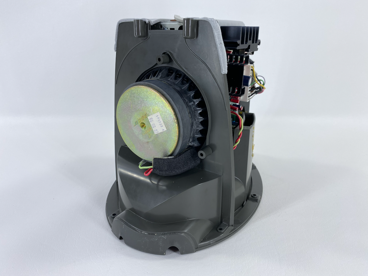
Rear view of base unit internals, showing the subwoofer magnet and cables.

TAM PSU and cables.

Inside the base unit casing, showing some of the sound-insulating foam.
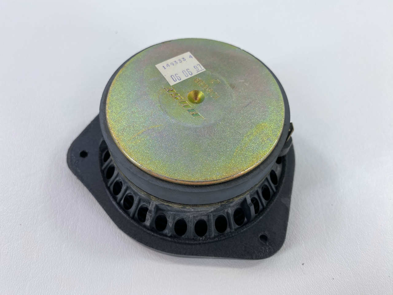
Rear of TAM Bose subwoofer, showing manufacture date of 06/06/1997.